Home Automation board crashes while running io test

Brecht

New member
Hello everyone,

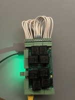
I'm testing with my newly acquired Home Automation v4 board.
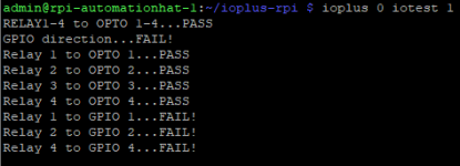
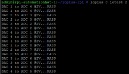
Unfortunately I run into some problems during the io tests, see screenshots below.

iotest 1.png
iotest 2.png
iotest 3.png

As you can see, there is a problem with relay 6 (i don't hear it clicking when i activate it with
Code:
ioplus 0 relwr 6 on
However, the biggest problem is iotest 1, this fails completly and my raspberry pi reboots at this point. I am clueless about the cause of this problem. Wiring seems okay, as it runs fine for the other iotests?

Any help would be greatly appreciated! Thanks
IMG_7729.jpeg
 

alexburcea

Moderator
Staff member
Hi,

The card you have is the newest version which GPIO's has been replaced by the one wire bus and RS485.
The GPIO test does not working anymore and the relay-opto test will pass if you unplug the connector from the rs485-one wire bus connector.
Sorry for the inconvenience but since you can use almost any of the Raspberry GPIO's having more on the card is useless and we do something more useful with the connector.
 

Brecht

New member
Thank you for your reply. Tested again and now it works fine.
Maybe it's worth to update the documentation of the board?

iotest 1b.png
 

nicolabeber

New member
Hi,

The card you have is the newest version which GPIO's has been replaced by the one wire bus and RS485.
The GPIO test does not working anymore and the relay-opto test will pass if you unplug the connector from the rs485-one wire bus connector.
Sorry for the inconvenience but since you can use almost any of the Raspberry GPIO's having more on the card is useless and we do something more useful with the connector.
Hello, could you kindly explain how use 1-wire bus? Thanks
 

alexburcea

Moderator
Staff member
Hi,

The one wire bus is used for many applications but in our case we use it to read the DS18B20 temperature sensor.
You can connect multiple sensors on the same port and the card will detect it and read each sensor.
The sensor has 3 wires, power, GND and data which must be connect to the corresponded pins of the card.
 

nicolabeber

New member
Hi,
yes I plugged in a ds18b20 sensor (I'm sure that it works because I used it on raspberry pico).
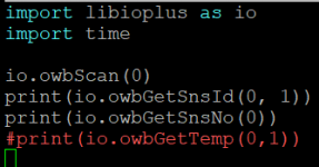
I write this simple code:

a.png

and this is the output

b.png

thanks for the the help.
Nicola
 

nicolabeber

New member
Another question: with the 1-wire bus managed by your board, what is the thoretical maximum distance at which the probes can be read without errors? I mean, usually if you plug a ds18b20 probe directly to raspberry you can read it at max 3-5 meters. If you use a good twisted and shield cable, maybe more. Thanks
 

alexburcea

Moderator
Staff member
Unfortunately I can not answer this question but I am sure better than with Raspberry because we use transistors to drive the line from 5V.
 
Top