Hi,
I am using the Industrial Hat to read a 4-20 mA input and have noticed significant oscillations in the readings. To investigate this issue, I set up a test with a continuous 8 mA current (according to a multimeter, which is not calibrated but should be fairly accurate).
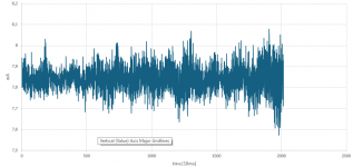
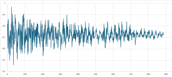
I read the incoming current using the get4_20In function with some different sampling frequencies (1s, 0.1s and 0.01s). I ran 4 tests and got the following result:
Test1: Avg: 7.84mA, Min:7.57mA, Max: 8.08mA
Test2: Avg: 7.84mA, Min: 7.54mA, Max:8.16mA
Test3: Avg: 7.82mA, Min:7.54mA, Max:8.17mA
Test4: Avg: 7.85mA, Min: 7.56mA, Max:8.15mA
While the average readings across all tests are close to the expected 8 mA, the variation within each test seems unusually high and concerning. I've attached a plot from one of the tests where the oscillation is clearly visible.
Is this level of fluctuation normal for a 4-20 mA input reading with the Industrial Hat?
Could there be any environmental or hardware-related factors causing this oscillation?
Any other suggestions or similar experiences?


