Home automation V3 - opto input - state reading

yepyep_ca

New member
Hi,

I installed a home automation V3 hat to a raspberry.
I am able to control the relays using python.

But I am not able to use the opto input channels.
I wired a sensor to the opto input 1 (I tried with 1, 2, 5 and 6...).
If I take a multimeter, I am reading 23.5V on the pin 1 of the hat but when I run the following code, python prints 0.

import libioplus as iop
print(iop.getOptoCh(0, 1))


Am i missing something ? (highly possible, I am beginner :))

Thank you
 

alexburcea

Moderator
Staff member
Hi,

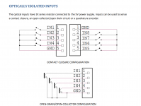
As you can read from the manual, the opto-inputs are pre-polarized to be able to read dry contacts with it.
Here a usage example from the manual:


Home Opto Inputs.png
 

yepyep_ca

New member
Thank you for your answer.
I am sorry but I don't know what "pre-polarized" means.
For my application, I have a sensor which sends 0V when not detecting and 24V when detecting something.
How can I get the state of this sensor ? on the raspberry
 

alexburcea

Moderator
Staff member
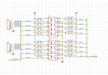
It means that the optocoupler is connected to 5V trough a 1k resistor.
Has_opto_sch.png

If your sensor does not have open-collector output you can not use it directly connected to the card.
 

Fabio

New member
Dear Alex, I am facing a big issue about OPTO-IN used with an switch. It often happen that the OPTO-IN self activate due to electrical noise..
Can you provide a solution ?
Previous version of card was not affected by this issue.
I can confirm that more than 20 IOPLUS old model card are working properly , but not the new one.
take care.
 

alexburcea

Moderator
Staff member
Hi, there is no change from the previous version regarding opto inputs. Please let me know what are the two versions you compare.
If the noise is the cause, you can use a capacitor in paralel with the switch or filter the data in software.

Alex.
 

Fabio

New member
I confirm the solution I applied is exactly adding capacitors..... i suggest you to make considerations about this, because this filtering can be already present on the board, and also splitting the resistor in 2 single resistors installed in LED-A and LED-K side ..... and also an ESD protection since those lines can be remoted ....
take care,
Fabio
 
Top