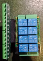
Home automation board old version details?

jacqu0

New member
I purchased one of these boards a while ago and am only now just getting around to using. However, the HW revision level has changed and the details/pinouts are different. Can you please provide a pointer to the old revision documents/drawings/specs etc?
Can I assume that the latest ioplus library is compatible?
Thanks in advance.
 

alexburcea

Moderator
Staff member
Before I can answer you have to tell me the hardware revision printed on the card or better if you can give me a picture of the top side of the card will be helpful.
 

alexburcea

Moderator
Staff member
You have a old version but is not the first, and the last ioplus is compatible with this version.
Attached is the old manual which has not been reviewed for a few years.
 

Attachments

  • HOME-Automation-UsersGuide.pdf
    961.8 KB · Views: 4

jacqu0

New member
Thank you for the quick response. Just what I was looking for. I'd forgotten what a fantastic board this is!

A further questions about the breakout board. There's no pin numbering on the io expander header. Which end is pin 1?

I need some code (preferably python to use the ioplus library) that enables me to control and read status of the various IO ports over mqtt to fit in with my target system. Do you, or anyone else, know if such code exists?

Cheers.
 

alexburcea

Moderator
Staff member
Look for the squared pad of the home card io header, and you will find the pin 1.
The card has python library to access it but I do not know anyone using it with mqtt. I think is more easy to do it in Node-RED if you did not work with mqtt in python.
 

jacqu0

New member
Hope you can help.

I can control the relays using the ioplus relwr command and get that status (relrd), but I am unable to get any readings from the opto or ADC inputs. I am using the breakout board (as per the photo above) and yes, I am aware that the pin number on the breakout board is reversed. When I use the commmand "ioplus 0 optred 1" and connect the GND or +3.3V to pin 3 (io port)/pin 38 (breakout board) I just get "0" returned. Same for all the other opto ports and the ADC ports. The same is true from within my python script using the libioplus .

The iotest's with the test board all PASS OK.

Am I missing something?
 

alexburcea

Moderator
Staff member
Hi,

The opto inputs anodes are all connected to OPTO VEXT and cathode to the corresponding channel. So you need to connect OPTO VEXT with +5V (strap between pins 2 and 4 of the header). For easy pins visualization, type "ioplus -pinout" in the terminal.
 

jacqu0

New member
Thank you. The OPTO VEXT connection was the missing piece.
I haven't seen that documented anywhere and the schematics just show +5V, that I assumed was internally connected.
 

jacqu0

New member
A further question on the OPTO inputs. I want to use them to detect a PIR detector event that swings to 12V (hardwired in sensors). What do I need to do for this? I'm assuming the OPTO VEXT would have to be connected to 12V as well but a external serial resistor should be added to the OPTO input to keep the current flowing roughly the same as the 5V supply, say an external serial R=1K. Makes sense?
 
Last edited:

alexburcea

Moderator
Staff member
The opto inputs series resistor (inside the card) is 1k, this means about 10mA when you put 12V at vext. The optocoupler maximum current is 50mA, but the only week part is the series resistor maximum power disipation wich is 100mW.
It might work without serries resistor but I recommend to use one about 5k.
 
Top